 Vintage Workshop
Services for Brough Superior motorcycles and their contemporaries
|
Vintage Workshop Services for Brough Superior motorcycles and their contemporaries |
KTOR JAP crankcase machining last update: 24-03-2004
First, I thought I might machine a one-off manually on a conventional milling machine. While planning this, I learnt that it is not even easy to hold the casting in a suitable way, let alone machine all the different bores for the cam bushes etc. in the two respective cases in a way that grants proper alignment.
Thus I thought about making all the proper jigs to hold the castings and CNC machine the whole lot. My good friend Thomas (who is rather into 60's and 70's Mercedes cars than vintage bikes, but a very keen engineer and quite a genius on the CNC mill) encouraged me to do just this and promised to help me along the way.
You may say CNC machining is cheating, and I cannot say a lot to my defence. But it will enable me to machine a small batch of castings once the first one looks good. And I learnt I am not the only lunatic trying to build an SS100 replica at the moment, so maybe I can help you out with a set of cases...
I had to learn, however, that trying to do it right from the start makes the whole thing a long, long way to go!
| I decided the first thing to machine is the outside of the lugs. This
will provide me with an opportunity to rigidly rig up the castings for the
machining of the mating surfaces, inside of crankcase and bearing seats in
one distortion-free set-up, as you will see later.
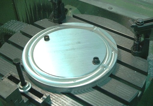
We could have clamped the casting directly on the machine table, but adjusting the position would have been a difficult job to be repeated on each casting. So we made jig No.1. Of course, the underside had to be machined first, with a centring recess for the centre of the table and a keystone for angular location. It does not look spectacular, but cost us quite a few hours! |
|
| Now we were able to clamp the casting onto this jig.
In order not to distort the casting, we put small strips of sheet metal underneath it in the three positions were the clamps were, thus avoiding any bending stresses. With the casting thus rigged up, we can face and drill the mounting lugs. |
|
| Same for the timing side half.
The timing chest will be machined later, as we want this to be perfectly aligned with the whole rest of the engine. |
|
| The jig for machining the inside of the cases will be a trifle more
complex.
This is the underside after facing it, inserting a centring plug, boring all the necessary holes and milling a key slot for the angular positioning. |
|
| On the upper side, we have now machined 6 recesses for the location of the 6 posts that will hold the crankcase lugs. |
|
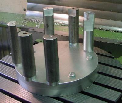
| Here, the posts have been inserted, but they still need machining on the top ends. So this is how far we are at the moment, but we will carry on.... |
|
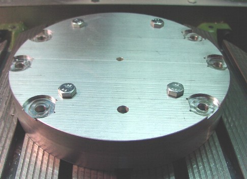
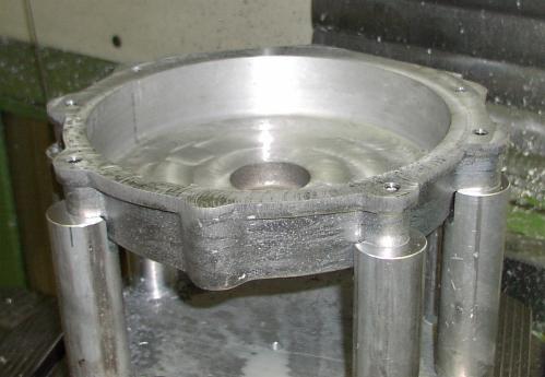
| Well, we have had another go. Now we have machined the top ends. Made
enough space for the crankcase castings to go in, faced the top ends, bored
and cut 6 mm threads in them and, most important, machined two very accurate
recesses in the middle struts to accept two hollow dowel pins that will
grant accurate alignment of each crankcase half.
If you have a close look at the picture above, you can see the respective recesses in the lugs of the castings. |
|
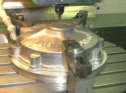
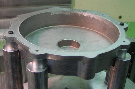
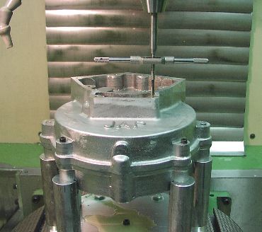
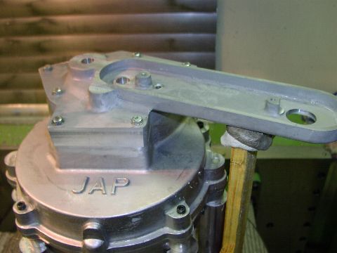
| Now this is how the crankcase sits in the jig. Why the tall studs you might ask? This is because we want to machine the cylinder base flanges and stud threads with the horizontal spindle, and this does not go too near to the milling table... As a first step, we hold it with two 6mm bolts (and said hollow pins) to machine 4 countersinks for the Allen screws that will lastly hold the work. Of course we will take out the 2 bolts and machine these position as well! |
|
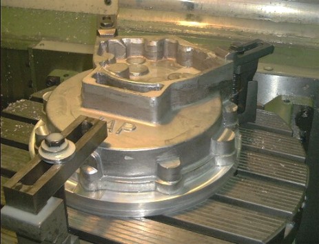
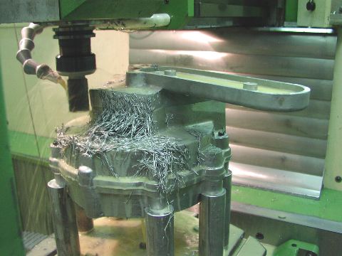
| Here the work is held with 6 Allen screws, and we have finally started
machining the mating surface and the inside of the crankcase.
By this way of rigging it up we can machine the mating surface and its spigot and the main bearing seats in one set-up, thus granting perfect alignment of the main bearings. Unfortunately we were none too happy with the surface we achieved. So I will have to have a special milling cutter made (a big end mill with a 3/16" radius ground at the edge) for machining the inside. |
|
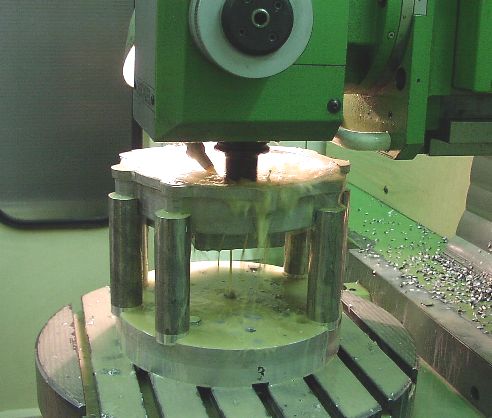
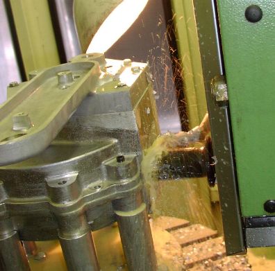
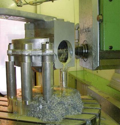
| 2/2004: The show goes on, albeit after a
long break!
I found a suitable indexable milling cutter and I even managed to find the proper carbide tips for it, i.e. highly polished ones that will not encourage the aluminium to build up near the cutting edge. This picture is just to give an impression of CNC milling. The hard fact is that you cannot see too well what is going on, so you just have to be sure what you programmed before you press the start button! |
|
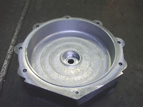
| This is the inside of the timing side half thus treated. I had to use another cutter for the jointing flange and spigot, and still another one to machine the bearing seat, of course. |
|
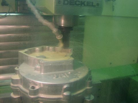
| Now the idea was to finish the inside of the timing side half first,
than take it off. Next finish the inside of the drive side half. Then, stack
the t/s half upon the finished d/s half for the machining of the timing
chest.
Of course, hollow dowel pins again between the two halves just in case we should like to take it off for a reason. Here, the jointing surface to the timing cover is being faced. |
|
| After CNC drilling the stud holes I found that none of the nice BSF and
Cycle taps I had bought would fit our tapping head.
So we used the CNC mill just to position a spring loaded centre (do you have one of these? Fantastic little things!) exactly above the stud holes to ensure absolute right angles while tapping by hand. |
|
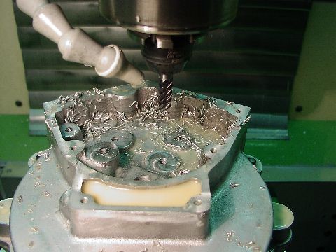
| Next, we centre bored and drilled all the holes for the camshafts, cam
follower pins, valve lifter bosses and the breather valve. And milled all
the corresponding faces.
And we milled all those cutaways that will (hopefully!) make sure that the cams are free to turn, the cam followers free to follow and the valve lifter levers free to lift. Only he who has done it before knows how many of these there are in a JAP engine! |
|
| The next item is the timing cover. The jointing face had been prepared on my trusty FP1 before... |
|
| ... so it could go straight upon the timing chest.
Mind you, the front camshaft bore has not been finished yet inside the timing chest, but carries a thread so I could align the timing cover and then bolt it down with an M10 bolt before drilling the stud holes in the same positions as before and milling the countersinks for the nuts. |
|
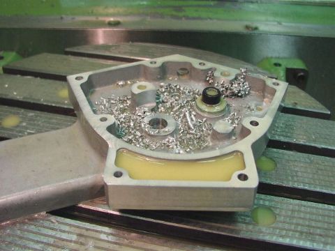
| Er, I found the casting was a trifle on the thick side underneath the
oil box so this was put right at once!
Other than that, no faults in the patternmaking have come to light yet , which is not too bad for a series 0. |
|
| For the machining of the chain cover face and the magdyno shaft hole, we
had to apply some means of damping to prevent the casting from vibrating.
Otherwise no big problems. You can see the bores for the camshaft bushes have also been made yet. Nothing metric, 11/16" diameter of course! I forgot to take a picture of this, but I aligned the chain cover on top of the lot and centre bored the screw holes in that as well. |
|
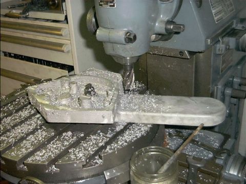
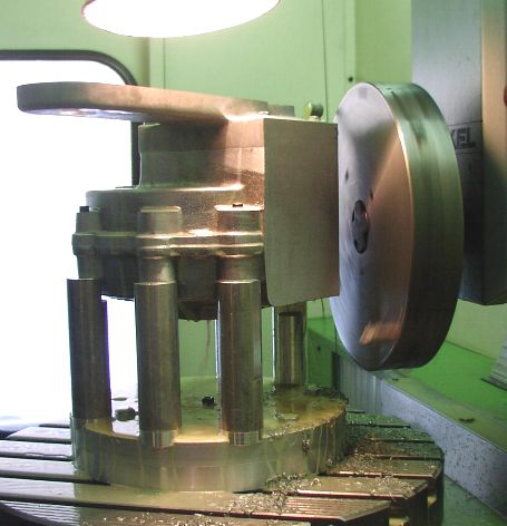
| Now it is time for swapping over to the horizontal milling axis (my
favourite one, indeed, as with almost any mill, this is the one that runs
much quieter and is much more rigid than the vertical one!) . Here that cylinder base flanges are being faced. |
|
| On a CNC mill, you can easily machine a bigger face with a smaller
cutter. But I decided the criss-cross-pattern of the cutter paths did not
quite look the part on top of the crankcase of a vintage engine.
So we used a good old-fashioned fly cutter for the finishing cut on these, and a massive one at that! |
|
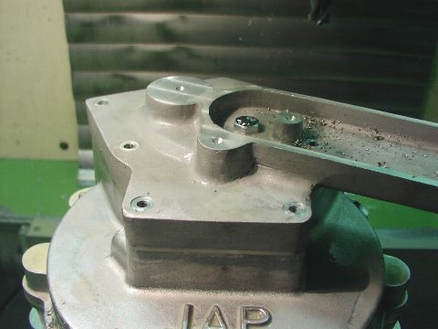
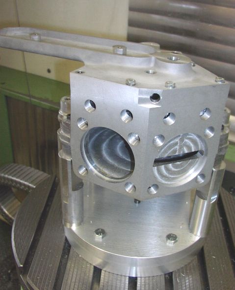
| Here, at last, you can see the crankcase mouth openings being machined. Now it starts looking like an engine! |
|
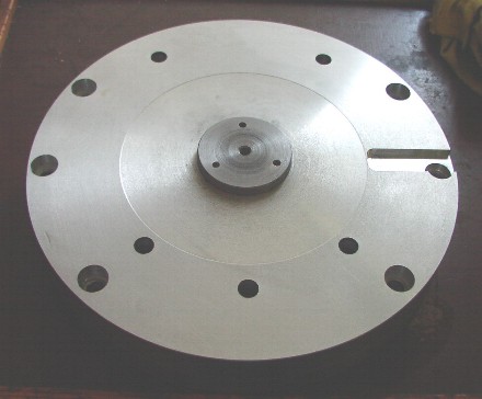
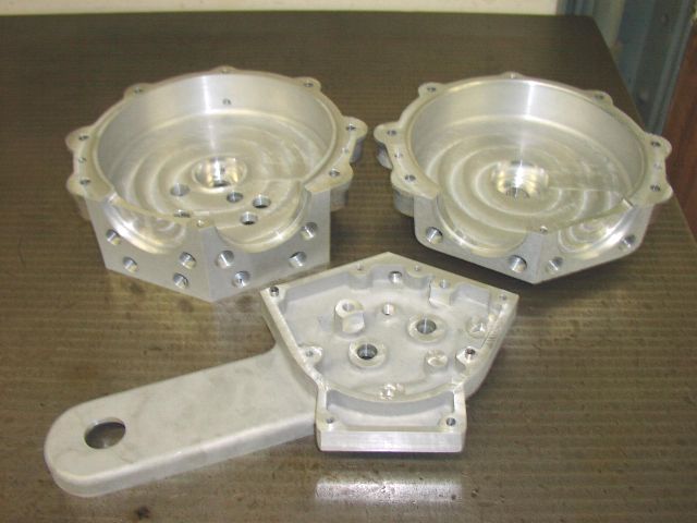
| 06.03.2004: This is how far we are.
For the thimbles I used a 3/4"x20 tpi thread. This is historically not quite correct as JAP's used the finer (26 tpi) thread up to the end of the 1927 season, but I think they did not make the change without a reason... |
|
| Well, a few little things needed doing inside the timing cover... |
|
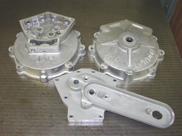
| But I think THAT'S IT NOW! |
|
| I hope you like the look of them... |
|
| Again, to spare you the trouble of writing a frustrated e-mail, and to
save me the embarrassment of answering it, making my excuses:
I am not producing these crankcases commercially and I am afraid I don't have any for sale! |
Any kind of feedback to
![]() is
appreciated
is
appreciated
(sorry, this is not a clickable 'mailto:' hyperlink. If you want
to write me, please type my address in your mailer. )